How to Hack an Alarm Clock
 Today I found out how to hack an alarm clock to do really cool things.
(note: This is a Sponsored Post written by me on behalf of Swiss Army Knives . All opinions however are 100% mine. If you are interested in picking up the Swiss Army Knife used in this article, you can do so here: Dual Pro X)
If you’re anything like me, the sound of your alarm clock rates somewhere between nails on a chalkboard and a Vuvuzela blown incessantly during the World Cup. This is primarily because the alarm clock basically is designed to rip you from your peaceful slumber and more often than not, force you to get out of a warm comfortable bed and step into an inevitably chilly room. Now, having to get up at a certain time is something that most of us can’t really get around. But I set about thinking about how I could accomplish this without being ripped suddenly from perhaps a deep sleep. Basically, I wanted an alarm clock that would wake me up more naturally.
The basic idea here to hack the alarm clock towards this end is simply to clip into the speaker wires and detect with a microcontroller when there is voltage being sent to the speaker. From that, you can tell whether the alarm clock is going off or not and have your microcontroller and circuit do all sorts of cool things.
In my case, I wanted it to flip on my heater and light (and a future add-on, open my blackout blinds) about 15 minutes before I actually wanted the alarm clock buzzer to go off. The light then will help my body wake up more naturally and the heat will make my bedroom nice and toasty for when I’m ready to get up. Then, when it’s finally time for me to actually wake up 15 or so minutes later, if I haven’t woken up and turned off my alarm yet, my alarm buzzer will actually go off to finish the process of waking me up. In this way, by the time my alarm clock buzzer goes off, my body will have already started waking itself up more naturally in response to the light and heat.
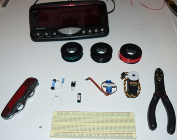
Materials Needed:
- Any old alarm clock with a speaker of some sort
- One microcontroller; I used a Basic Micro Nano 18, but pretty much any microcontroller with an analog to digital converter will do. Note: the code for the Basic Micro Nano 18 should translate with very little or possibly no modification to any basic stamp.
- One 1K resistor
- One 5 volt normally open reed relay
- One 5 volt regulator
- One 10uF capacitor
- Two servo motors with sufficient torque to flip a light switch and, in my case, turn a heater adjustment knob
- Misc wire
- Wire cutters
- One knife or wire strippers; I’ve always preferred to just use a pocket knife, which, with a little practice, is just as fast as wire strippers and works better than quite a lot of wire strippers I’ve used over the years. Victorinox was nice enough to send me a new Dual Pro X Swiss Army Knife to replace my old pocket knife I used to use for stripping wires, among other things. So I’ll be using that in this how-to, along with giving a small review on the pocket multi-tool at the end of this article. Also, if you’ve never used a knife to strip wires before, skip to the end of the article for a short little tutorial on how to use a knife to strip wires quick and easy.
- Phillips or flat head screw driver (in my case, I just used the Dual Pro X’s built in Phillips screw driver)
- Breadboard; In this how-to I’m just showing a breadboarded version of the mod. In a later how-to article, on how to easily print circuit boards from home, I’ll demonstrate how to convert this to a nice circuit board version that will easily fit in the alarm clock case.
- Soldering iron / solder (for connecting power to the circuit from the alarm clock; alternatively you could just use a 9 volt battery for testing purposes)
- One multimeter
*warning: probably doesn’t need to be said, but be sure and unplug your alarm clock before taking it apart lest you electrocute yourself.
Step 1:
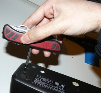 Locate the screw holes that hold your alarm clock together. On my old alarm clock, which incidentally I’ve now had for around 15 years, the screw holes are on the bottom.
- Remove the screws holding the case together.
Step 2:
- Locate the wires from the alarm clock board running to the speaker.
- Clip the wires somewhere in the middle, leaving yourself enough room to be able to strip the wires back a bit on each side to eventually connect to.
- *note: I clipped the ground side too, so I could run a wire from that ground onto my circuit so they share a common ground; alternatively you could just solder a wire onto a ground on the alarm clock circuit board itself and leave that wire uncut.
Step 3:
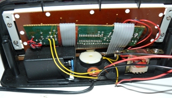 Connect wires running from each of the ends of the now clipped speaker wires to the circuit board.
- One end of the +V speaker wire (the end coming from the circuit board) should be hooked up one end of the relay and to an ADC pin on the microcontroller. I also used a 1K resistor from here to the ground. Depending on the voltage your alarm clock is sending along the speaker wire, you may need to adjust that to get a good reading on that pin.
- The other end of the +V speaker wire (the end going to the speaker) should be hooked up to the other end of the relay so that when the relay is flipped on, the two ends are connected and thus the buzzer will kick on like normal.
- The ground wires should be hooked to a common ground on your breadboard.
Step 4:
- Use your multimeter to locate a 5-12 volt supply of power on your alarm clock circuit board that you can tap into to power your circuit.
- Once you’ve located this power source, solder a wire onto this and connect it to your circuit’s 5 volt regulator.
- note: I chose to include a 5 volt regulator on my circuit even though the voltage from my alarm clock circuit board was already 5 volts. I did this just as a sort of “just in case” as I’m not sure if the particular place I tied in to ever changes voltage or how good of quality the regulator on my alarm clock is.
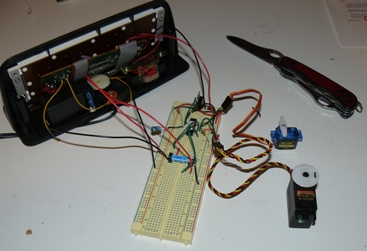 Now from here, we have a nice base to work with where we can detect with a microcontroller if the alarm is going off or not and also have the ability to flip on or off the buzzer with the microcontroller and the relay.
Rather than listing the rest of the steps involved in putting together my particular circuit, I will just leave you with some pictures of the circuit and a circuit diagram; so if you’d like to make this exact circuit yourself, you can. I have also included my code which is written in Basic and hopefully documented well enough that it should make sense to anyone who wants to take a look at it or modify it for their own particular uses.
Links:
- Completed Code (should be able to open it with notepad if you don’t already have a program installed that can open it)
- Circuit Diagram (in the form it needs to be for making the printed circuit board, which I will do in a future article on “how to easily make a printed circuit board from home”)
- Circuit Diagram PCB file (can be opened with a myriad of different programs, the one I use is Pad2Pad, which is free)
- Large Version of the Complete and Functional Breadboarded Circuit (note: the green wires on the left side of the chip with the 10K resistor are only there for programming the chip purposes; they would be removed in the circuit boarded version)
How to Strip Wire With a Knife:
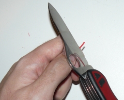 If you’re going to use a knife to strip a wire and have never done so before, it’s really easy and fast. The basic method I use is as follows. First, I cut into the wire insulation until I feel the knife scrape against the metal a little. Now angle the knife so you won’t be cutting into the wire and strip the insulation off that side of the wire. The basic idea here is very similar to how you’d peel a carrot or potato.
Now, you could continue this on the other sides, but I’ve found this is not typically necessary. Having exposed one side of the wire, go to the opposite side and cut into the wire until you again have cut through the insulation.
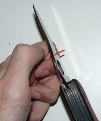 Now rather than angle the knife to scrape the insulation off this side like on the other side, this time keep the knife at a 90 degree angle to the wire and pull the insulation off using the knife. If the insulation is too thick, you might need to peel one of the other sides first. But for small wire like is used in most electronics projects like this, I’ve found that is usually not necessary.
Now do the other side and you should have a nicely stripped wire as shown here using the above method
Now the Dual Pro X Swiss Army Knife I used in doing this how-to does have a wire stripper built in and it worked pretty well, but I still prefer just to do it using the above knife method. If you happen to have a Swiss Army Knife or other multi-tool, you’ll notice that many include a wire stripper. With the Swiss Army Knife, it is usually a notch in one of the tools, such as the screw driver or can opener.
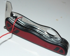 Using it is fairly simple, you basically want to open the tool half way (it should lock half way for this purpose), then open an adjacent blade a little. Place the wire in the notch and apply some pressure with the blade, then pull the wire. The wire seems to strip great every time, but as I said, I still prefer the knife method.
Dual Pro X Swiss Army Knife Review:
- note: despite this article being sponsored by Victorinox, I am fully at liberty to say anything I want, good or bad, about the Swiss Army Knife they sent me to use in this how-to article.
- Positives:
- Like any other Swiss Army Knife I’ve ever seen, it seems very high quality.
- Blades are very sharp and seem really strong.
- I love the new locking mechanism, which differs from my old Swiss Army Knife a bit. The new method is a “one handed” release system where you press over, rather than down, with your finger and can fold the blade back then using just the one hand. My old one used a spring loaded lock, similar to this, except you had to press down very hard. This new way is much easier.
- This model Swiss Army Knife also has some rubber lining around the outer edges, which give a nice grip and helps it from slipping around wherever you set it. This also differs from my old one, which was all metal casing.
- Negatives:
- Although this model has plenty of tools built in, I really would have loved wire cutters.
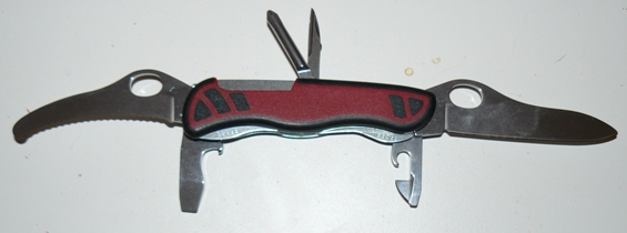
- The blade on the back is extremely stiff and not too exposed, so a little hard to open unless you have fingernails.
- Overall, this is a nice high quality little multi-tool, as you would expect being a Swiss Army Knife.
Bonus Facts:
- The term “Swiss Army Knife” was coined by United States soldiers after WWII. The soldiers had trouble pronouncing the original name of “Offiziersmesser” and thus just began calling the multi-tool a “Swiss Army Knife”.
- Victorinox, the company that makes Swiss Army Knives, was named after the founder Karl Elsener’s deceased mother. Her name was Victoria. The “nox” part comes from the fact that stainless steel is also known as “inox”, which is short for the French term “inoxydable”, hence “Victorinox”.
- Karl Elsener himself was originally the owner of a surgical equipment company. He later took over production of the original Modell 1890 knives, which were previously made in Germany. He moved the production to Switzerland and greatly improved the design of the original multi-tool. The breakthrough came when he figured out a way to put blades on both sides of the handle using the same spring to hold both sides in place. This allowed him to put twice as many features into the multi-tool as was previously possible.
- There exists a Swiss Army Knife that has 314 tools built in, which is a world record.
- Victorinox manufactures over 50,000 Swiss Army Knives a year for the Swiss army alone.
- The Swiss Army Knife is part of a standard equipment kit carried by each NASA astronaut in space.
| Share the Knowledge! |
|



todayIfoundout:
Today’s article was totally different from previous articles. How to hack an alarm clock?
Today’s content was completely different from previous posts. I don’t recall any recent “How to hack an electronic like they do on other web sites to do stupid stuff” articles on this site. this site is about making me smarter, not about turning me into Hank Hill.
I understand the need for a sponsor, but don’t grasp at straws desperate for an article you can publish that would require the use of a swiss army knife.
Regards,
Ryan
@Ryan: Actually, this was an article I had already planned on doing and the sponsor more or less fell in my lap on it. I like to put some interesting how-to’s in here and there, if you check the how-to section (and in the past these have been very popular). The sponsor had nothing to do with whether I posted this article or not. However, I realize particularly the electronic how-to’s are not everybody’s cup of tea. This is why, when I do a how-to article, I always post another article on the same day (usually directly after I post the how-to article). When I posted this how-to article, I also posted this one, which is probably more to your liking: Today I Found Out Chef Boyardee Was a Real Person
ANNNNNNnnnnnd you still clicked on it? go away and spend your free time doing something productive. this how to is what helps me wake up in the morning. Sorry that you have no reason to do so.
Very cool article, I would like mine to turn on the lights, then maybe flip my bed over when I dont get up lol. New Graham Knives at http://www.newgraham.com is a great place I have found to buy swiss army knives or any other kind, just my 2 cents worth, and I have used Swiss army knives for yearsm so handy.
A few of the links above (circuit diagram, PCB layout, etc) don’t work. I wonder if you could repost them somewhere so I that I might take a look. I am very interested in this project. Thanks!
Indeed, even here in belgium, we’d like to see those documents… in order to hack my alarm clock… 🙂
Thank you in advance!
Would it be possible for someone to make a video that shows exactly how to do this? If so please notify me. Thank you.
Why not just use a time switch to turn the items on …
Should be “How to turn an alarm clock into a lamp timer”.
I’m just trying to add a speaker to my alarm clock. It was dismantled. How would I do it?
Should be “How to turn an alarm clock into a lamp timer”.